Client
Ms A. abcd
123 Route de abcd
Installer
AC Climatisation – Banne
Pieter MIGO
SIRET: 993 834 019 00016
TVA: FR71 993834019
1. Quote
Following our appointment, I am sending you my quote for the supply and installation of a reversible air conditioning system (air-to-air heat pump).
During my visit, I was able to look carefully at the house and the different rooms. What stood out immediately was the very high quality of the renovation, carried out with real attention to detail. Even the technical spaces are particularly clean and well finished.
I work very precisely myself and care a lot about neat finishing. It is therefore natural for me to deliver the installation with the same level of care. During the work, I work cleanly, keep the site tidy and make sure everything is left in order.
You indicated that you would like the project to be fully completed by 1 July. I will take this into account in my planning and allow enough time to carry out the installation properly.
Purpose of the installation
The main purpose of the installation is efficient and comfortable cooling:
-
Second floor
-
Child's bedroom: ± 4.60 m × 4.20 m
-
Main bedroom: ± 4.00 m × 5.00 m
-
Third floor
-
Large open living space: ± 4.70 m × 8.50 m
-
Front left bedroom: ± 3.50 m × 4.40 m
-
Front right bedroom: ± 4.30 m × 3.30 m
The installation can of course also be used for heating, which provides additional comfort in the shoulder seasons and in winter. I return to this point when discussing the choice of units.
In this configuration, it makes sense to use two multi-split outdoor units, one per floor.
2. Situation and power advice
The rooms on the third floor have a sloping ceiling height of approximately 2.50 m to 4.00 m, which has an important impact on the required capacity. Because of the larger air volume and the build-up of heat under the roof, the cooling demand here is noticeably higher than in rooms with a standard ceiling height.
The estimate below is based on the dimensions of the rooms, the ceiling height and an average insulation level. It remains a guideline; the final unit selection will be refined according to the desired comfort level and the position of the indoor units.
| Room | Area (approx.) | Cooling capacity | Heating capacity |
|---|---|---|---|
| Child's bedroom (2nd floor) | 19 m² | 2.0 – 2.5 kW | 2.5 – 3.0 kW |
| Main bedroom (2nd floor) | 20 m² | 2.0 – 2.5 kW | 2.5 – 3.0 kW |
| Large open space (3rd floor) | 40 m² | 4.5 – 6.0 kW | 5.0 – 6.5 kW |
| Left bedroom (3rd floor) | 15 m² | 1.5 – 2.0 kW | 2.0 – 2.5 kW |
| Right bedroom (3rd floor) | 14 m² | 1.5 – 2.0 kW | 2.0 – 2.5 kW |
Translation into system choice (multi-split)
Based on these capacities, it is logical to work with one multi-split system per floor.
Second floor
- Total cooling demand: ± 4.0 – 5.0 kW
- Total heating demand: ± 5.0 – 6.0 kW
👉 Advice:
- Multi-split outdoor unit in the ± 4.0 to 5.0 kW class (nominal cooling capacity)
- Indoor units slightly oversized for quiet and comfortable operation
Third floor
- Total cooling demand (theoretical simultaneous use): ± 7.5 – 10.0 kW
- Total heating demand: ± 9.0 – 11.5 kW
👉 In practice:
- the large room and the bedrooms are rarely used at maximum output at the same time
- the load is therefore spread over time
👉 Effective simultaneous cooling demand: ± 6.0 – 8.0 kW
👉 Advice:
- Multi-split outdoor unit in the ± 9.0 kW class
Although this may seem generous on paper, it is a deliberate choice here:
- the large room under the roof heats up significantly
- a more powerful indoor unit (± 5 to 6 kW) has been selected
- and there is a need for fast and comfortable cooling
👉 By choosing a slightly larger outdoor unit:
- the installation can handle peaks without difficulty
- the units run more calmly and quietly
- and real-life efficiency remains high
👉 Because simultaneous use is limited, this is not structural oversizing, but rather a stable, comfort-oriented installation
Important nuance
With multi-split systems, the total capacity of the indoor units is often higher than the capacity of the outdoor unit. This is normal and allowed for by the manufacturer.
The final choice will be matched to:
- simultaneous use
- comfort (noise versus capacity)
- the technical limits of the selected system
3. Efficiency and electrical consumption
Given the number of rooms to be conditioned, the efficiency of the installation is a very important point. A well-chosen system provides comfort, while keeping electrical consumption under control and reducing energy costs over time.
Air-to-air heat pumps work with high efficiency, expressed as COP (heating) and EER (cooling). In practice, this means that for every 1 kW of electrical power, approximately 3 to 4 kW of heating or cooling is delivered.
Required electrical power
Based on the estimated capacities above:
- Indicative total cooling capacity: ± 11 to 15 kW
- Indicative total heating capacity: ± 13 to 18 kW
With a realistic efficiency (COP/EER ≈ 3 to 4):
- Required electrical power when cooling: ± 3.0 to 5.0 kW
- Required electrical power when heating: ± 3.5 to 6.0 kW
⚠️ These are simultaneous peak loads. In practice, the units rarely all run at full power at the same time, so actual consumption is usually lower.
Importance of efficiency
Given the number of rooms to be conditioned, the efficiency of the installation plays a crucial role. A considered choice of units provides comfort while keeping energy use controlled in the long term.
Air-to-air heat pumps typically achieve a COP/EER of around 3 to 4, which means they can deliver significant heating or cooling capacity with limited electrical input.
In practical terms:
- electrical consumption remains relatively low, despite the number of rooms
- the units run more calmly and quietly, because they do not need to operate continuously at maximum output
- comfort is more stable, without large temperature swings
Correct sizing and unit selection are therefore essential to actually achieve this efficiency in use.
4. Electrical connection
Given this power level, it is necessary to provide a dedicated supply line from the electrical panel to the outdoor unit(s).
Proposed execution (sufficient for the current installation)
- Dedicated protected circuit (20 A, depending on the final configuration)
- U-1000 R2V 3G6 mm² supply cable, suitable for outdoor use
- Installation of a local isolator near each outdoor unit
➡️ This option is technically sufficient for the planned installation
Adaptation in the electrical panel
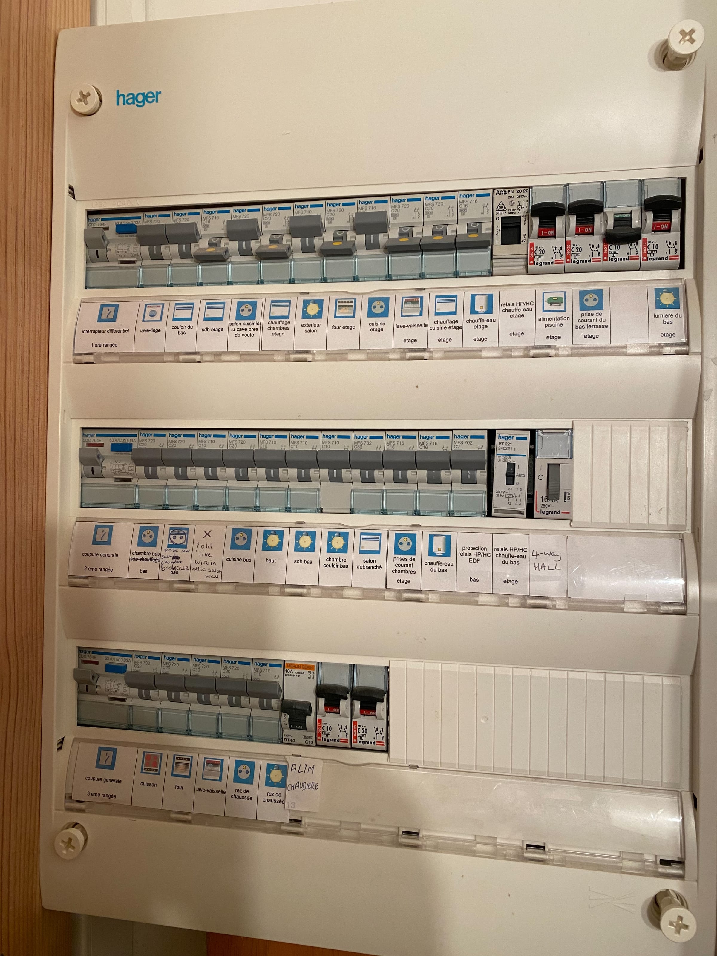
Here you can see a photo of the existing electrical panel.
The panel still has room on the bottom row to add a 20 A circuit breaker.
For this quote, I plan to replace the existing interrupteur différentiel on the bottom row with a type A, combined with a 20 A circuit breaker for the air conditioning supply.
The current installation is fitted with type AC interrupteurs différentiels. For modern inverter air conditioning systems, the NF C 15-100 standard requires a type A differential. This is suitable for leakage currents that may include a DC component, which can occur with this type of equipment.
With this adaptation, the new circuit is carried out in a way that is suited to the load type and compliant for this new circuit.
It is also visible that a large number of circuits is currently connected to each differential (around 14), while the standard is based on a maximum of 8 circuits per differential. This has no direct impact on the new installation, but may affect the selectivity and reliability of the protection in the longer term.
👉 Note: this quote only includes the necessary adaptation for the air conditioning. A more complete modernisation and redistribution of the panel can be carried out later if desired.
Routing of the supply line
Overall, the supply line runs from the electrical panel towards the solar panels. From there, it passes through the large room on the 3rd floor to the loft space, then follows the air conditioning pipework outside.
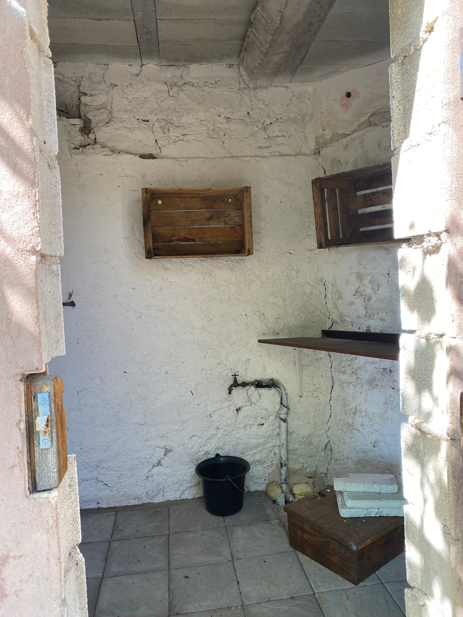
From the panel, the supply line goes to this room. The existing solar panel cable also runs here. In this first section, the new cable can in principle be laid neatly alongside it.
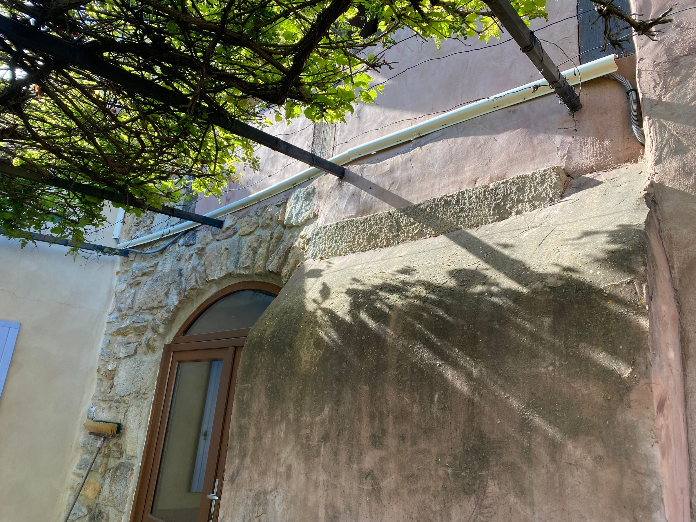
From this room, the supply line goes outside and passes above the vine, preferably through the same trunking.
If there is not enough space, a wider trunking will be needed. This is not currently included and would then be handled on a time and materials basis.
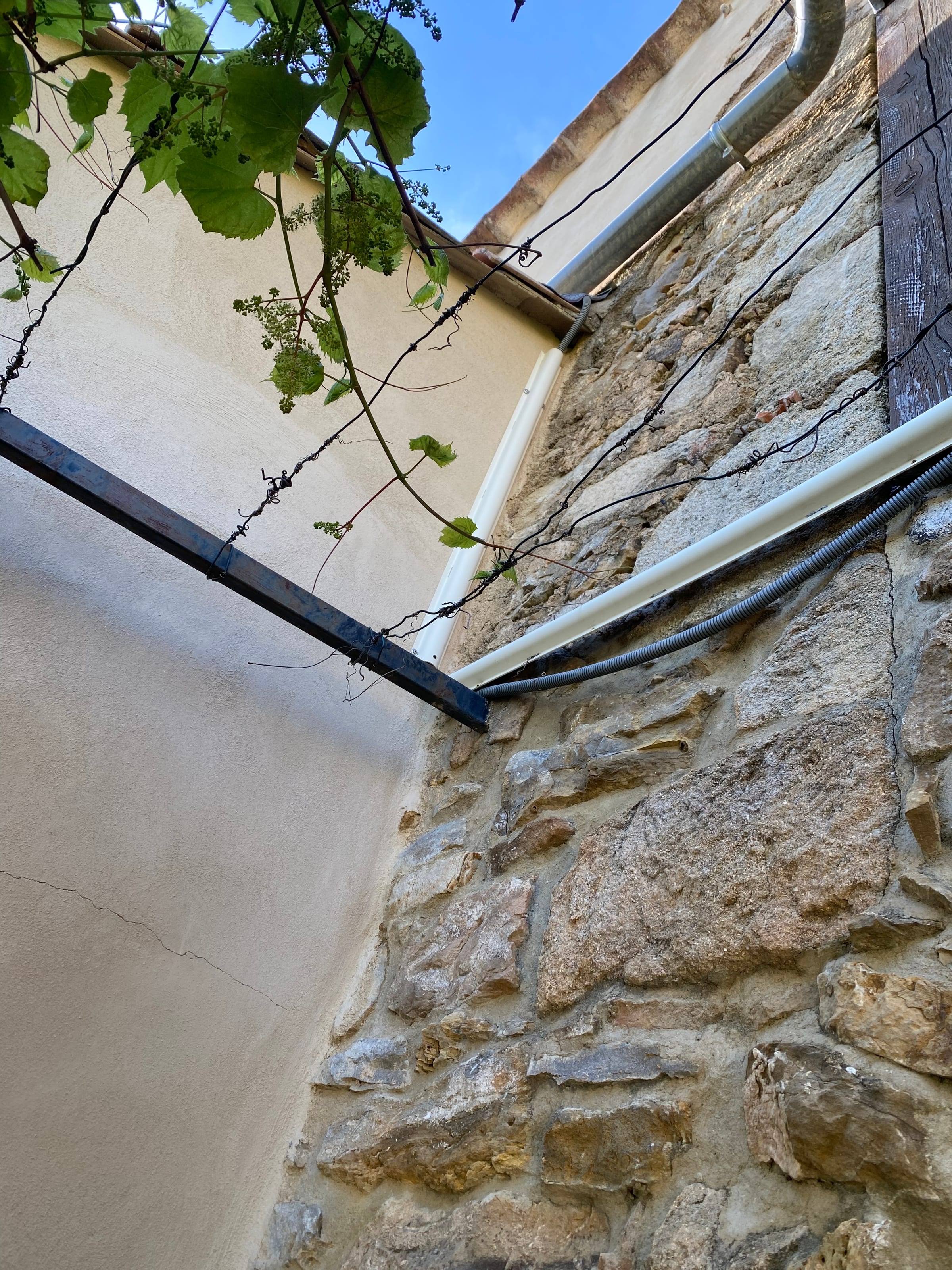
The existing trunking is not very firmly fixed at the moment. I will pay extra attention to this and refix it properly.
The cable then goes up, is protected under the rainwater downpipe, crosses a small part of the roof and enters the large room on the 3rd floor.
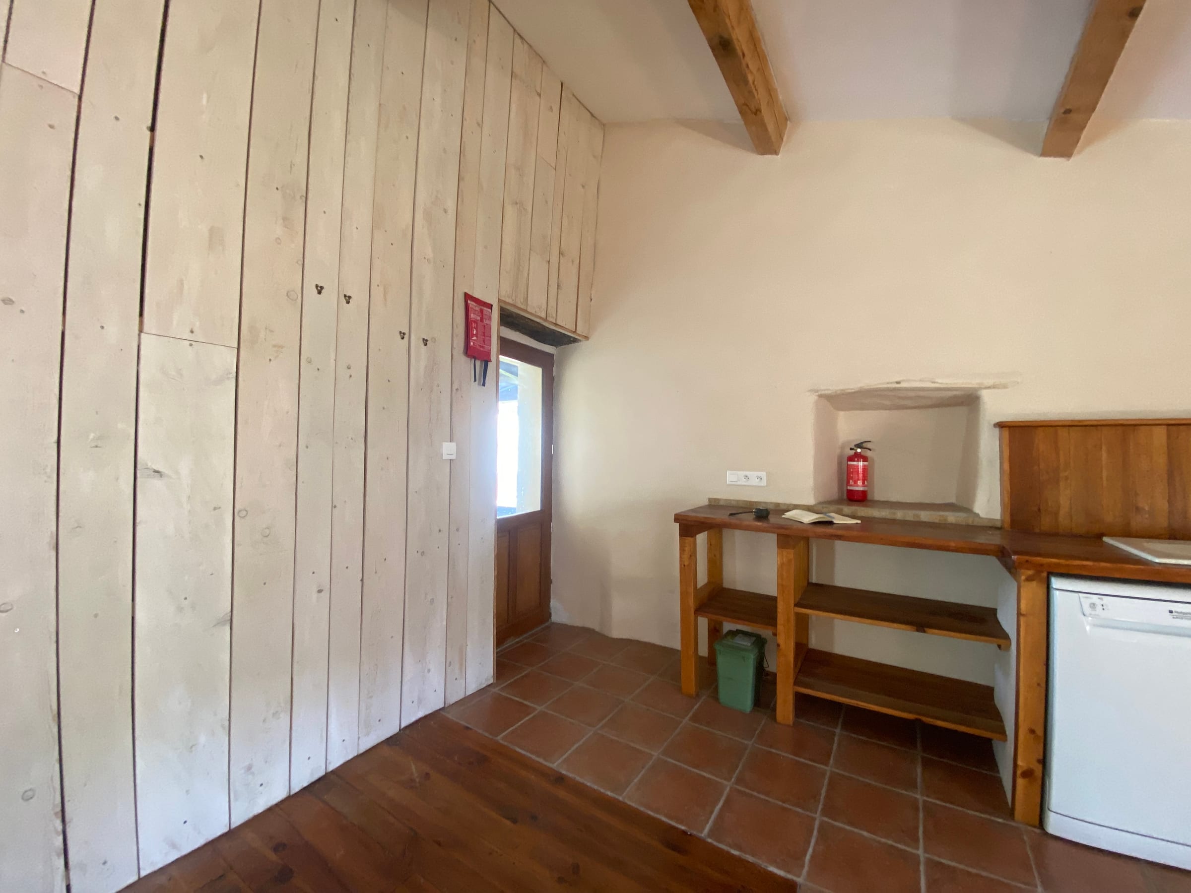
The cable enters behind the door. A slight bump is visible here, probably an existing service. I will therefore stay deliberately well to the left.
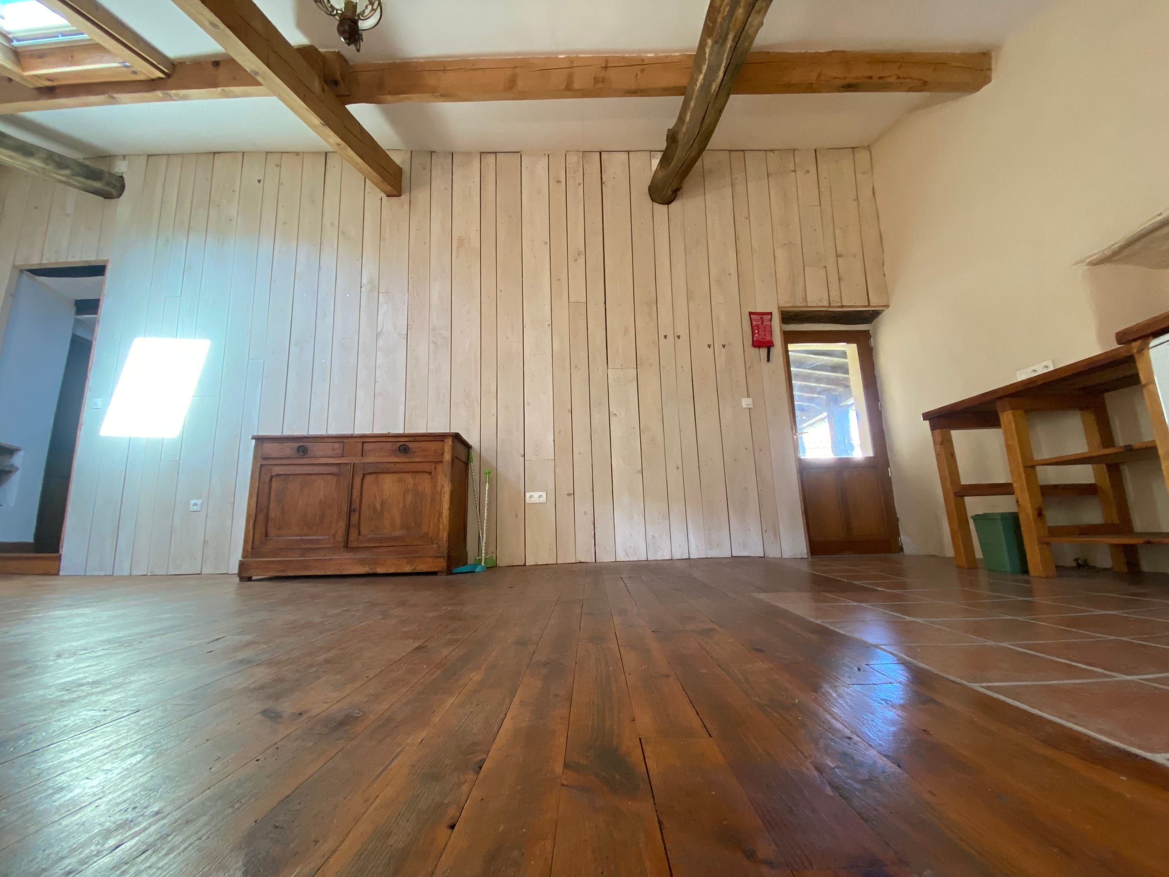
Option 1 — Behind the timber slats (recommended)
The long wall on the third floor is finished with timber slats, with existing services already behind them. The neatest, and actually the most logical, solution is to hide the cable completely behind these slats.
- In the end, you see nothing
- The outside view remains calm as well (vine + solar panels)
- It is easier if access is ever needed later
The cable route is:
- outside, about 2 metres up along the facade
- entering the room and going behind the slats about 3 metres to the left
- then going up to the loft space
- after that, it follows the air conditioning pipework
Where needed, I will remove slats. They will be marked and reinstalled exactly in the same place; normally this will not be visible afterwards.
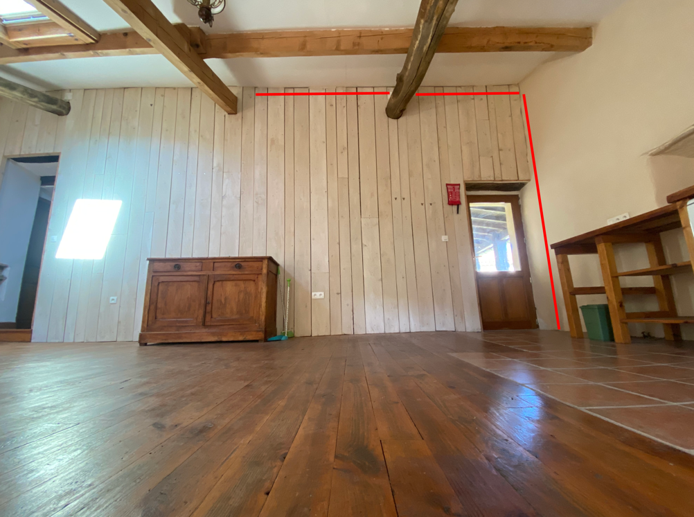
Option 2 — Visible trunking (not my preference)
It is also possible to do this more simply by installing the cable in visible trunking over the wall and above the beam.
- Less work
- Faster
But:
- Less attractive
- More awkward if access is needed later
Personally, I would not choose this unless there is a specific reason. In the image, this option is shown in red.
5. Placement of the indoor units and routing of the pipework
All indoor units will be positioned so that condensate water can drain naturally. This means no condensate pumps are needed, making the installation quieter, more reliable and easier to maintain.
Third floor
All indoor units will be placed above the doors. For all rooms, the loft space is directly behind the wall. A hot water tank is located in this loft space and plays a central role in draining the condensate.
I have chosen to bring the refrigerant pipework from the 3 rooms to be cooled out through the wall adjacent to the large room. This is the least complicated solution and the least visible from inside.
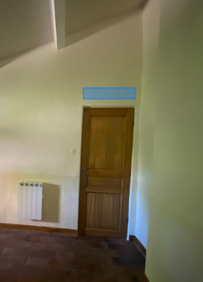
Front left bedroom
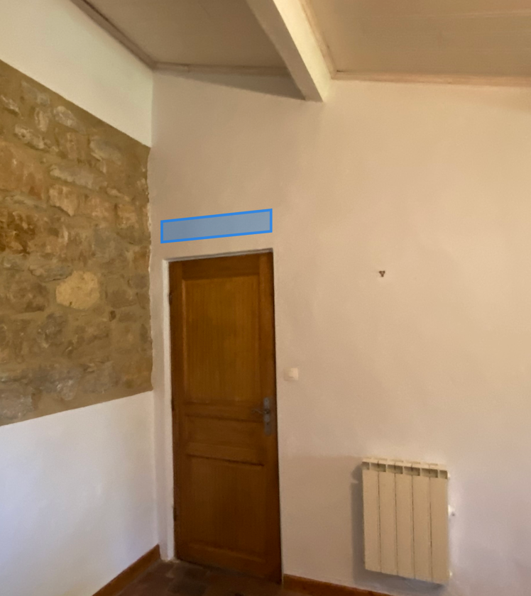
The blue marking shows the indoor unit above the door. The loft space is directly behind this unit.
The refrigerant pipework and condensate drain will be taken directly into the loft space, so they are not visible in the room.
In the loft space, the pipework will be neatly run in air conditioning trunking along the wall and below the hot water tank.
The condensate drain from this unit will be connected to the hot water tank drain.
Front right bedroom
Here too, the indoor unit will be placed above the door. The loft space is again behind this unit, allowing the condensate drain to be hidden and connected to the hot water tank drain.
Several lines come together to the right of this unit:
- the pipework for this unit
- the pipework from the other bedroom unit
- the supply line from the loft space
They will then pass through a core hole in the wall into the large room. In this way, three sets of refrigerant pipework come together here.
This is not possible directly from the loft space because of the position of the hot water tank.
The wall to the right of the unit will be finished smooth but left unpainted.
Large open space
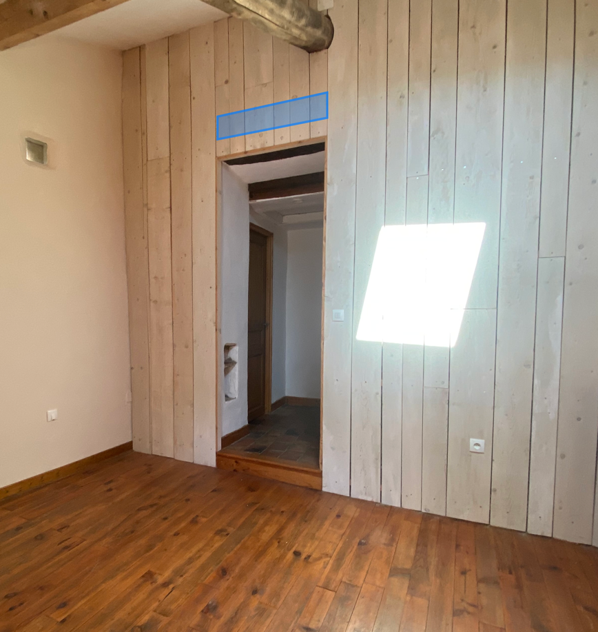
The blue marking shows the indoor unit above the door. The loft space is directly behind this unit, with a hot water tank nearby.
The condensate drain from this unit will be connected directly to the drain near the hot water tank. For this, an opening of about 25 mm will be made just below the tank. This means the drain does not need to go outside, saving space and giving a neater result.
The refrigerant pipework for this unit will preferably be hidden behind the four timber boards on the left. Space will be made in the wall for this (wall thickness approx. 60 cm, so there is enough margin).
The pipework from the two other units also comes together at this point.
The three sets of refrigerant pipework and the supply line will then go together to the outside. The only visible part will be a short trunking section of about 25 cm, neatly finishing the penetration to the outside. The exact height, near the window or lower near the ground, will depend on the conditions on site. My preference is as low as possible, because this limits the height needed for the outside scaffold.
Second floor
The main bedroom and the child's bedroom are adjacent and share about 2 metres of internal wall. From this floor, the most logical and least invasive solution is to run the refrigerant pipework from both rooms through the outside wall of the child's bedroom.
Rear main bedroom
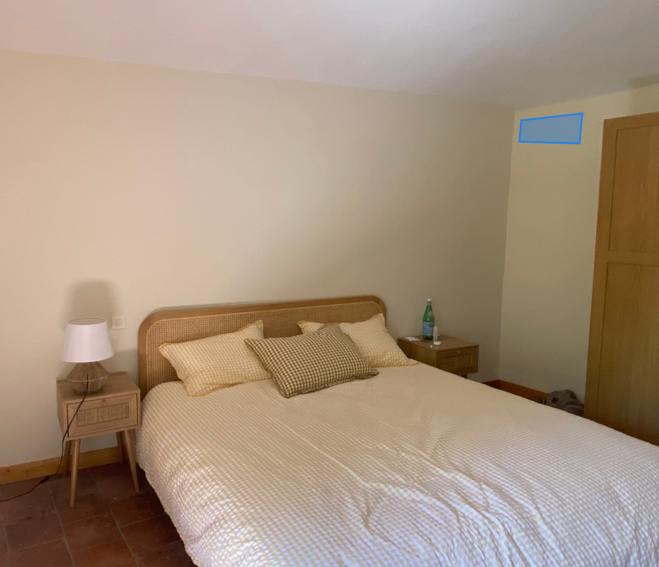
The blue marking shows where the indoor unit can be placed.
The child's bedroom is directly behind this unit. The condensate drain and refrigerant pipework will pass through a wall penetration into that room. As a result, there will be no visible trunking in the main bedroom.
It is advisable not to place a tall wardrobe directly next to this wall. If that is planned, we can look together at an alternative solution.
The indoor unit can be set to blow to the right.
✅ Location 0: this location is currently included in the quote
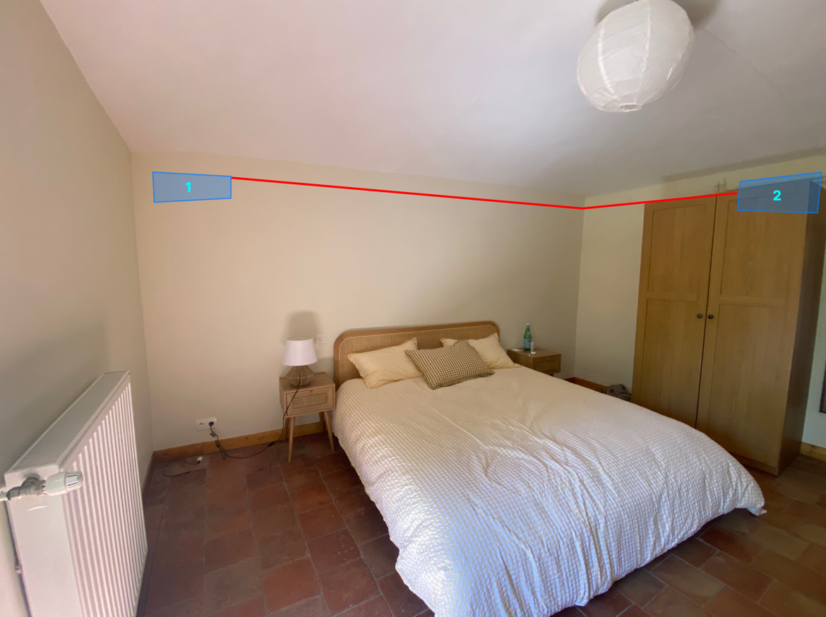
These are alternative locations for the indoor unit. In my view, it could also be placed above the door. I do not currently have a photo of that location. The smallest 60 mm trunking will be used.
⬜ Location 1: left of the bed
⬜ Location 2: halfway along the wall, between the door and the head side of the wall
⬜ Location 3: above the door
Extra care will be taken to ensure smooth condensate drainage. The additional cost is € 999,99 (HT).
Child's bedroom
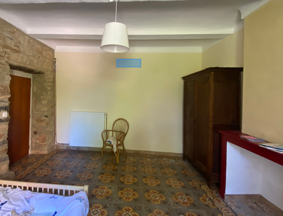
The blue marking shows the indoor unit.
Visually, the neatest position is approximately in the middle of the room. I would still like to confirm with you whether this is also the most practical position.
The refrigerant pipework from the main bedroom enters to the left of this unit. From here, both sets of pipework will be routed outside together, preferably about 10 cm from the outside wall of the main bedroom.
A short piece of air conditioning trunking may be needed on the left side of the unit. This depends on:
- the exact wall thickness
- and the angle at which drilling is possible
If the wall is damaged at this point, it will be finished smooth but left unpainted. If everything lines up neatly, this will not be necessary; it is roughly 50/50 depending on how it works out on site.
6. Placement of the outdoor units
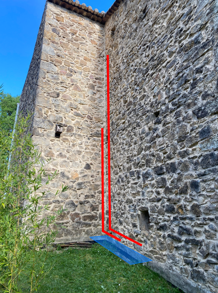
Pipework
For the pipework and drilling, and for safety, I will use a small work scaffold.
The neatest and most natural exterior solution is to run the pipework down through a rainwater downpipe (Ø100 mm) and bring it out at the bottom near the outdoor units.
The following finishes are possible, in order of durability:
- Zinc → the most durable and aesthetic, blends well with the house (indicative price about 2× compared with galvanised steel)
- Galvanised steel → strong and reliable, with a slightly more industrial appearance
- PVC → technically acceptable, but visually the least refined and less durable in the long term
Placement The most practical solution is to place the two outdoor units on a concrete slab, each separately on Big Foots.
Advantages:
- protected from vegetation and grass (débroussaillage)
- units stand slightly higher → better service life
- easy to access for maintenance
The layout is as follows:
- left: dual split
- right: triple split
The supply line terminates in a central junction box. Each unit will have its own local isolator, so it can be switched off separately for maintenance.
7. Technical execution and work progress
Core drilling
Large penetrations are made from inside with a dust-extracted, air-cooled diamond core drill (approx. 60 or 100 mm). Drilling to the outside is carried out with water cooling, to keep dust and damage to a minimum.
Pipework
All refrigerant pipework is brazed for a durable and leak-tight connection. At the outdoor unit, a safe service connection is used.
After installation, you receive a full measurement report for both cooling and heating operation.
The refrigerant pipework is:
- neatly taped
- fitted with protected insulation
- protected against weather and birds
Working method and cleanliness
During the work, I work as cleanly and neatly as possible. At the end of each working day, the spaces where work has taken place are tidied and cleaned, to keep disruption to a minimum.
During the work, I take photos and share progress by WhatsApp, so you remain properly informed.
Please note There is currently no service layout plan available. If one exists, please send it to me beforehand so I can take it into account as much as possible.
I will do everything reasonably possible to avoid hitting existing services or installations, but this can never be fully excluded. Please let me know in advance where water and electricity can be shut off if needed.
Any repair work will be carried out on a time and materials basis.
Liability is excluded for damage resulting from:
- hitting non-visible services (water, drainage, electricity)
- leaks or water damage resulting from this
- cracking or detachment of plaster during drilling
- damage to existing finishes (plaster, paint, tiles) around work zones
- limited damage to existing trunking or fixings during reuse or adaptation
All visible openings and worked areas will be carefully and neatly finished, with a smooth finish suited to the existing surface, but they will not be painted.
8. Selected units
Choice of units – Toshiba
For this project, I propose the Toshiba Shorai Edge. This system offers a very good price-quality ratio and reliable performance, especially for cooling.
Toshiba is known for efficient operation and stable performance. For applications mainly focused on cooling, it is a solid and durable choice.
Feature overview
| Feature | Toshiba Shorai Edge |
|---|---|
| Cooling efficiency | A++ to A+++ |
| Heating efficiency | A+ to A++ |
| Noise level | Very quiet |
| Modulation | Good |
| Design | Clean, slightly technical |
| Price | Favourable |
👉 Note: if a black finish is desired for the interior, the Toshiba Shorai Edge is a suitable choice.
App control
The system can be controlled via a smartphone app, allowing you to:
- control the temperature per room
- set schedules
- operate the installation remotely
The app is functional and easy to use, with all the necessary functions for daily use.
Summary
The Toshiba Shorai Edge is a reliable and efficient solution, mainly focused on cooling comfort, with a favourable investment level.
I propose this solution when the priority is:
- an efficient and comfortable cooling system
- a good balance between performance and budget
- an aesthetic integration (for example black indoor units)
9. Configuration of indoor and outdoor units
Toshiba Shorai configuration
Third floor
| Component | Model | Indicative capacity |
|---|---|---|
| Outdoor unit | RAS-4M27G3AVG-E | ± 9 kW class |
| Large room | RAS-B18 Shorai edge blanc | ± 5.0 kW |
| Left bedroom | RAS-B10 Shorai edge blanc | ± 2.5 kW |
| Right bedroom | RAS-B10 Shorai edge blanc | ± 2.5 kW |
Total connected capacity: ± 10.0 kW Number of ports used: 3 / 4
€ 999,99 HT € 999,99 HT Price for this equipment.Second floor
| Component | Model | Indicative capacity |
|---|---|---|
| Outdoor unit | RAS-2M18G3AVG-E | ± 5.0 kW class |
| Main bedroom | RAS-B10 Shorai edge blanc | ± 2.5 kW |
| Child's bedroom | RAS-B10 Shorai edge blanc | ± 2.5 kW |
Total connected capacity: ± 5.0 kW Number of ports used: 2 / 2
€ 999,99 HT € 999,99 HT Price for this equipment.10. Financial specification
Total calculation
The amounts below are deliberately fictional and only show the structure of the quote.
❄️ Toshiba Shorai
| Description | Quantity | Price excl. VAT | Total excl. VAT |
|---|---|---|---|
| Electrical supply | |||
| Electrical supply – 50 m (3G6 mm²) | 1 | € 999,99 | € %% ROW_MUL(2,3) -> line,material,options %% |
| HAGER Interrupteur différentiel 63A 30mA type A | 1 | € 999,99 | € %% ROW_MUL(2,3) -> line,material,options %% |
| HAGER 20A circuit breaker and accessories | 1 | € 999,99 | € %% ROW_MUL(2,3) -> line,material,options %% |
| Exterior galvanised finishing trunking (rectangular) | 7 | € 999,99 | € %% ROW_MUL(2,3) -> line,material,options %% |
| Outdoor unit local isolator | 2 | € 999,99 | € %% ROW_MUL(2,3) -> line,material,options %% |
| Junction box | 1 | € 999,99 | € %% ROW_MUL(2,3) -> line,material,options %% |
| IRL conduit, fixing material | 1 | € 999,99 | € %% ROW_MUL(2,3) -> line,material,options %% |
| Labour electrical panel | 3 | € 999,99 | € %% ROW_MUL(2,3) -> line,labor,options %% |
| Labour exterior pipework | 8 | € 999,99 | € %% ROW_MUL(2,3) -> line,labor,options %% |
| Labour for installing and hiding the supply line behind the timber slats | 16 | € 999,99 | € %% ROW_MUL(2,3) -> line,labor,options %% |
| Third floor | |||
| Toshiba multisplit installation for the 3rd floor (outdoor unit + 3 indoor units) € 999,99 HT | 1 | € 999,99 | € %% ROW_MUL(2,3) -> line,material %% |
| Double refrigerant pipe 1/4'' - 1/2'' | 1 | € 999,99 | € %% ROW_MUL(2,3) -> line,material %% |
| Double refrigerant pipe 1/4'' - 3/8'' | 2 | € 999,99 | € %% ROW_MUL(2,3) -> line,material %% |
| 16 mm condensate drain pipe | 1 | € 999,99 | € %% ROW_MUL(2,3) -> line,material %% |
| 4-core connection cable (indoor / outdoor unit interconnection) 4G1.5 flexible | 3 | € 999,99 | € %% ROW_MUL(2,3) -> line,material %% |
| Diamond core drilling for pipework passage | 3 | € 999,99 | € %% ROW_MUL(2,3) -> line,material %% |
| Labour installation 3rd floor | 18 | € 999,99 | € %% ROW_MUL(2,3) -> line,labor,options %% |
| Second floor | |||
| Toshiba multisplit installation for the 2nd floor (outdoor unit + 2 indoor units) € 999,99 HT | 1 | € 999,99 | € %% ROW_MUL(2,3) -> line,material %% |
| Double refrigerant pipe 1/4'' - 3/8'' | 1 | € 999,99 | € %% ROW_MUL(2,3) -> line,material %% |
| 16 mm condensate drain pipe | 1 | € 999,99 | € %% ROW_MUL(2,3) -> line,material %% |
| 4-core connection cable (indoor / outdoor unit interconnection) 4G1.5 flexible | 2 | € 999,99 | € %% ROW_MUL(2,3) -> line,material %% |
| Diamond core drilling for pipework passage | 2 | € 999,99 | € %% ROW_MUL(2,3) -> line,material %% |
| Labour installation 2nd floor | 12 | € 999,99 | € %% ROW_MUL(2,3) -> line,labor,options %% |
| Exterior finishing and placement | |||
| Scaffold provision (transport, assembly, dismantling) | 1 | € 999,99 | € %% ROW_MUL(2,3) -> line,labor,options %% |
| Concrete made of sand, gravel, cement and water, including formwork, light reinforcement, film and small materials | 1 | € 999,99 | € %% ROW_MUL(2,3) -> line,material,options %% |
| Zinc rainwater downpipe finish Ø100 mm | 15 | € 999,99 | € %% ROW_MUL(2,3) -> line,material,options %% |
| Bigfoot | 2 | € 999,99 | € %% ROW_MUL(2,3) -> line,material,options %% |
| Labour, preparation, pouring and finishing concrete slab | 8 | € 999,99 | € %% ROW_MUL(2,3) -> line,labor,options %% |
| Exterior finishing of pipework route | 8 | € 999,99 | € %% ROW_MUL(2,3) -> line,labor,options %% |
| Commissioning | |||
| Consumables (nitrogen, brazing material, gas, various accessories) | 5 | € 999,99 | € %% ROW_MUL(2,3) -> line,material,options %% |
| Vacuuming, brazing, commissioning and measurement report. The installation is pressure-tested with nitrogen and vacuumed according to good practice. | 8 | € 999,99 | € %% ROW_MUL(2,3) -> line,labor %% |
| Labour excl. VAT | € %% labor_ht = 0 -> summary %% | ||
| Materials excl. VAT | € %% material_ht = 0-> summary %% | ||
| Total excl. VAT | € %% total_ht = 888 -> summary %% | ||
| VAT 10% | € %% tva = PERCENT(total_ht, 10) -> summary %% | ||
| Total incl. VAT (before rounding) | € %% total_ttc = total_ht + tva -> summary %% | ||
| Rounding | € %% arrondi = ARRONDI_AUTO_BELOW(total_ttc) -> summary %% | ||
| Total incl. VAT (rounded) | € %% total_ttc_arrondi = total_ttc + arrondi -> summary %% | ||
Important note This quote is based on the information currently available. Work or supplies that are not explicitly mentioned may be invoiced additionally after discussion with you. Small usual additional work and small materials are included and are not invoiced separately.
12. Planning
You indicated that you would like the project completed before 1 July. As agreed, if the quote is accepted in time, I will give priority to this project so that we can do everything possible to meet this planning.
13. Reduced VAT rate of 10%
For homes older than 2 years, a reduced VAT rate of 10% may apply to renovation and improvement work. This applies both to labour and to supplied materials.
TVA 10% applies when the client signs the Cerfa n°1301-SD (attestation simplifiée) form beforehand. With this form, you declare that the property meets the conditions. Without this form, the standard VAT rate of 20% applies.
14. Time and materials
Unforeseen work outside this quote:
€ 999,99 per hour excl. VAT15. Service and maintenance
For optimal operation, hygiene and service life, I recommend that the installation is professionally cleaned, checked and measured once a year.
Maintenance rate:
€ 999,99 per year
The first service visit is included and will be carried out within the first year after installation.
Regular maintenance helps to:
- maintain efficiency
- reduce energy costs
- extend service life
- preserve warranty conditions
16. Acceptance
With this installation, you choose a quiet, comfortable and energy-efficient solution for cooling and supplementary heating.
If you agree, please sign the quote.
Place: ……………………
Date: ……………………
Client signature: _____________________
Conditions
- Work starts after acceptance of the signed quote.
- 30% deposit on order.
- Payment upon receipt of invoice.
- Manufacturer warranty according to manufacturer terms.
17. Possible phasing of the work
You indicated that it may be desirable to carry out the project in two phases, for example the second floor this year and the third floor at a later stage.
Technically, this is possible, but it has several important consequences.
Technical points
If the third floor is carried out later, there are two possibilities:
-
Either the pipework and penetrations for this floor are prepared now. This limits more invasive work later, but means that temporary pipework or provisions will be present before everything is fully finished.
-
Or everything is carried out later. In that case, the exterior work, routing and site organisation will largely have to be set up again.
Financial impact
The current price is based on carrying out the full project in one go. This makes best use of:
- combined labour hours and organisation
- one-time scaffold setup and exterior work
- efficient pipe routing
- combined supply and installation of several units
If the work is carried out in two phases, these advantages are partly lost. The total cost (phase 1 + phase 2) may therefore be higher than the price for carrying out everything in one go.
Practical approach
If you would like to consider this scenario, I can prepare a clear breakdown with:
- a price for carrying out the second floor;
- possible preparation for the third floor;
- an indicative price for the later work.
I suggest only developing this further if it is actually the direction you want to take, so the comparison remains clear and accurate.
Advice
My preference is to carry out the full project in one go. This gives the best result in terms of finishing, efficiency and total cost.
AC Climatisation
Comfort, efficiency and careful workmanship.